Circuit board business cards
have been done. But since circuit boards are, literally,
my business,
I felt that I needed one too. Of course it also had to be special.
Research and experimentation took a long time with this one and the
design even sat dormant, ready, for a while before I sent it out to fab.
 |
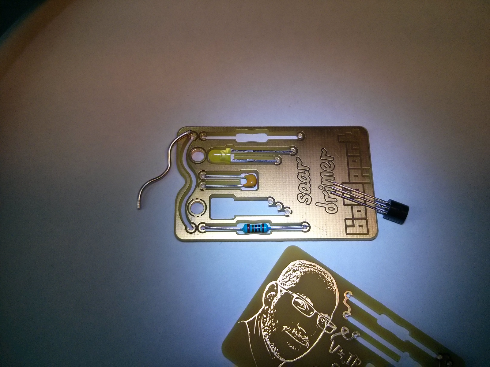
| Without components |
The concept was to have throughole components embedded within the PCB
and soldered lying down. The components -- two resistors, LED, NPN
MOSFET, and a capacitor -- form a complete circuit so that when voltage
is applied, the LED turns on.
 |
| Sizing up the components. Notice the wiggly piece of solder that fits into one of the slots. |
It's meant to be an engineer's emergency kit. When all hope is lost, the
MacGuyver engineer
could snap out one of the components and save the day. Recall the
countless times you desperately needed a 1 KOhm resistor to fix an
amplifier at a party, only to see the girl you were trying to impress
slip away with an
OCaml programmer? Never again with this little kit.
You even have 2 cm of solder in there to make sure the connection's electrically solid!
 |
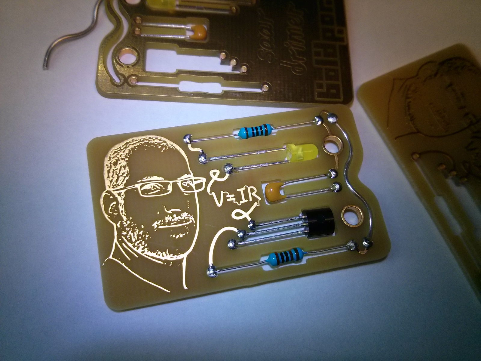
| Components soldered into place (top side) |
Consider the times when you were too drunk to recall Ohm's Law, yet was
called in to fix a spaceship's control system. V=IR is written on the
board to rescue you into awesomeness in spite of your inebriated state.
 |
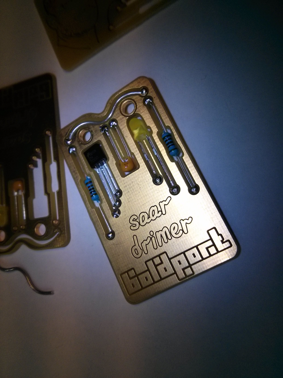
| Components soldered into place (bottom side) |
For those extreme situations when you need a
Winston Wolfe
my details are there so you know who to contact when the going gets
tough. Finally, as motivation, my disapproving mug is there to stare at
you as you're going about your engineering super hero day.
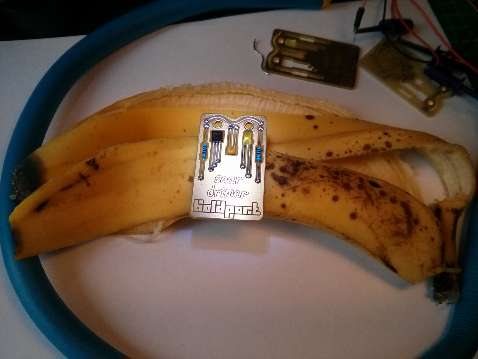
 |
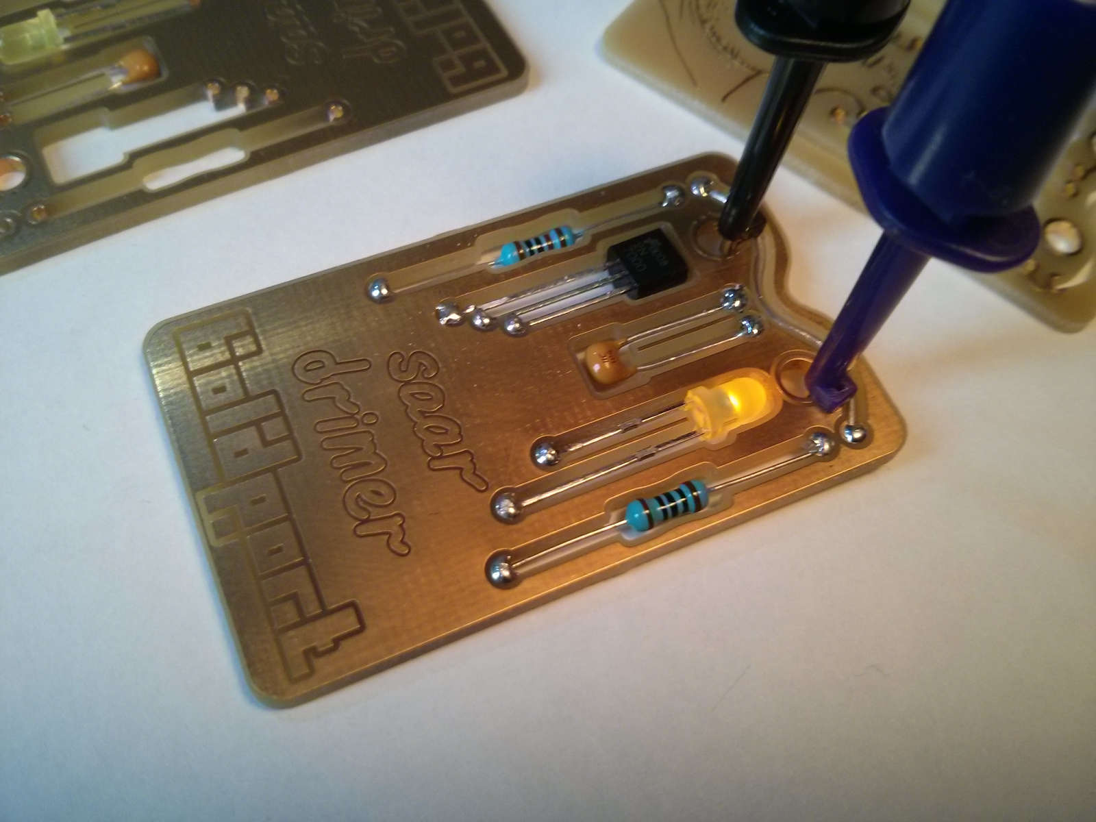
| It's a functional circuit! The LED lights up when you apply power. |
The board was manufactured by
PCB-POOL, without soldermask or silkscreen and using their default ENIG finish. This was the first
PCBmodE
board I've made with this fab, and they've done a great job. I
particularly like that they send pictures of the board during the
manufacturing process.
Now I only need to figure out how to manufacture this design cheaply enough so I can actually give those kits away ;)
 |
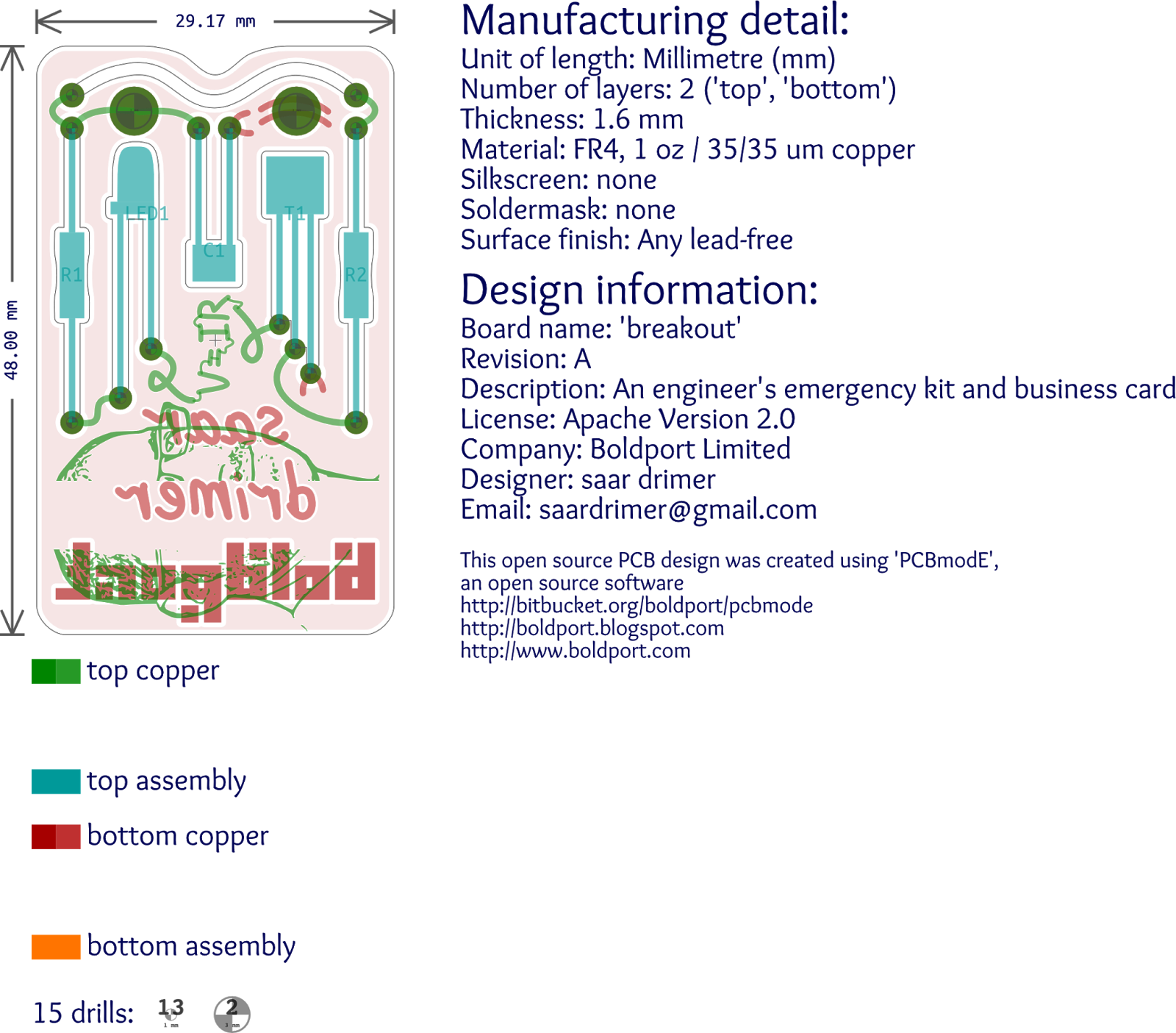
| A view from
Inkscape/PCBmodE. The assembly layer was used to size the cutouts. (That
break in my face is an artefact from Inkscape's bitmap export.) |
(Oh, this is an open source design! The source files are at the usual place in the
PCBmodE repository.)